


- Furniture and Architectural Hardware
- Search by Series
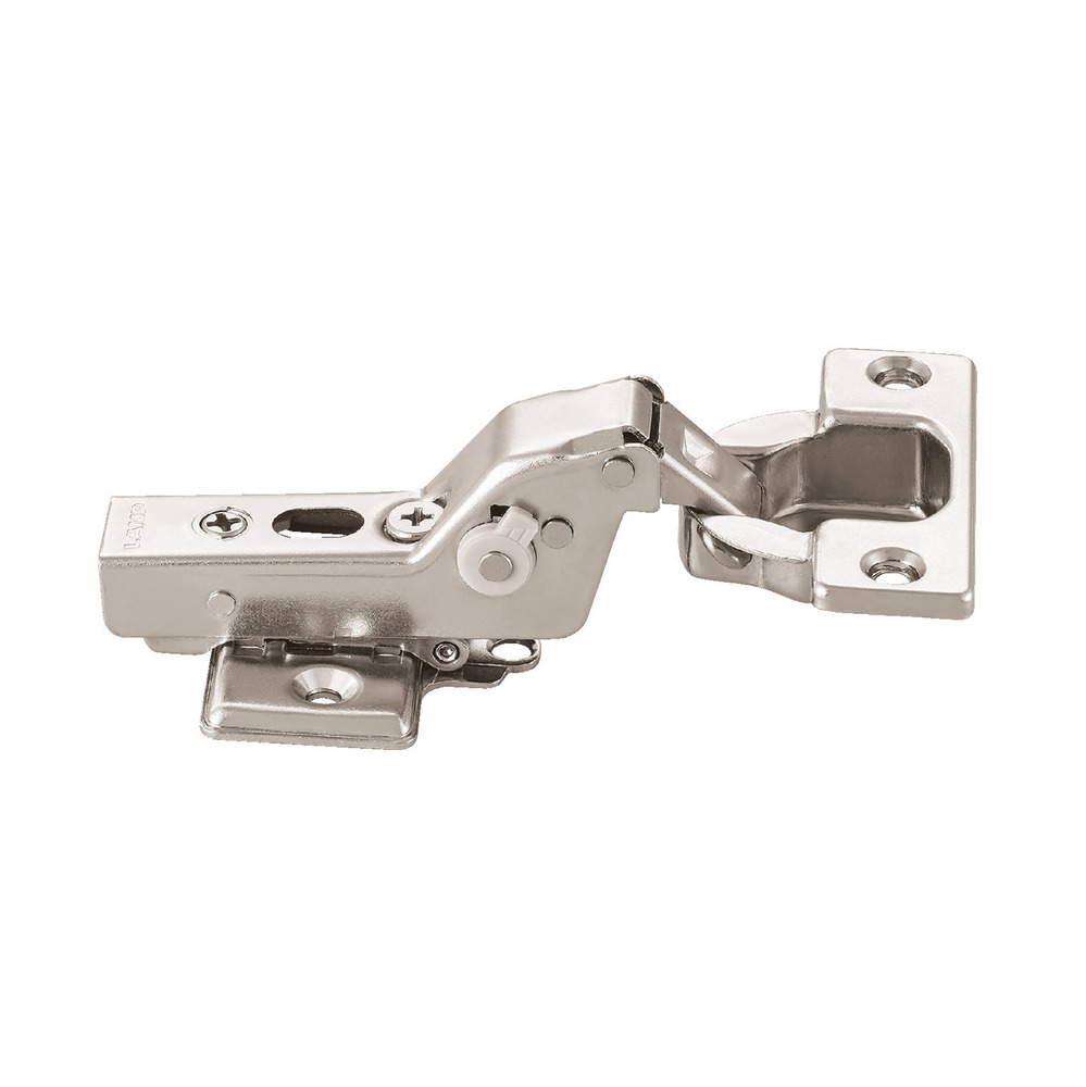
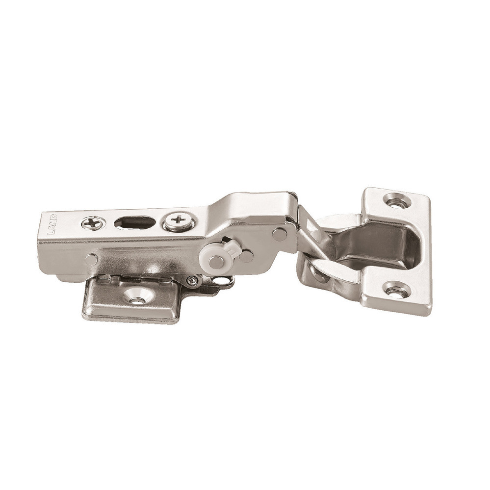
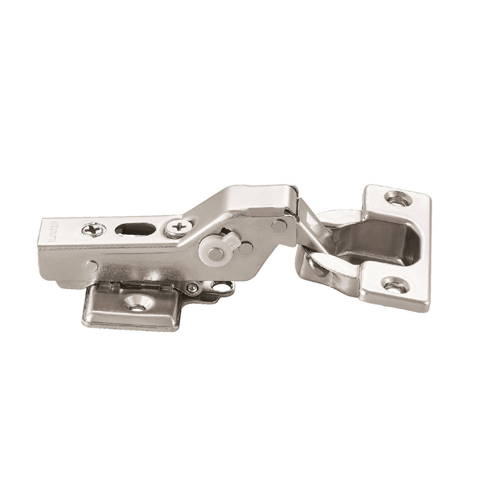
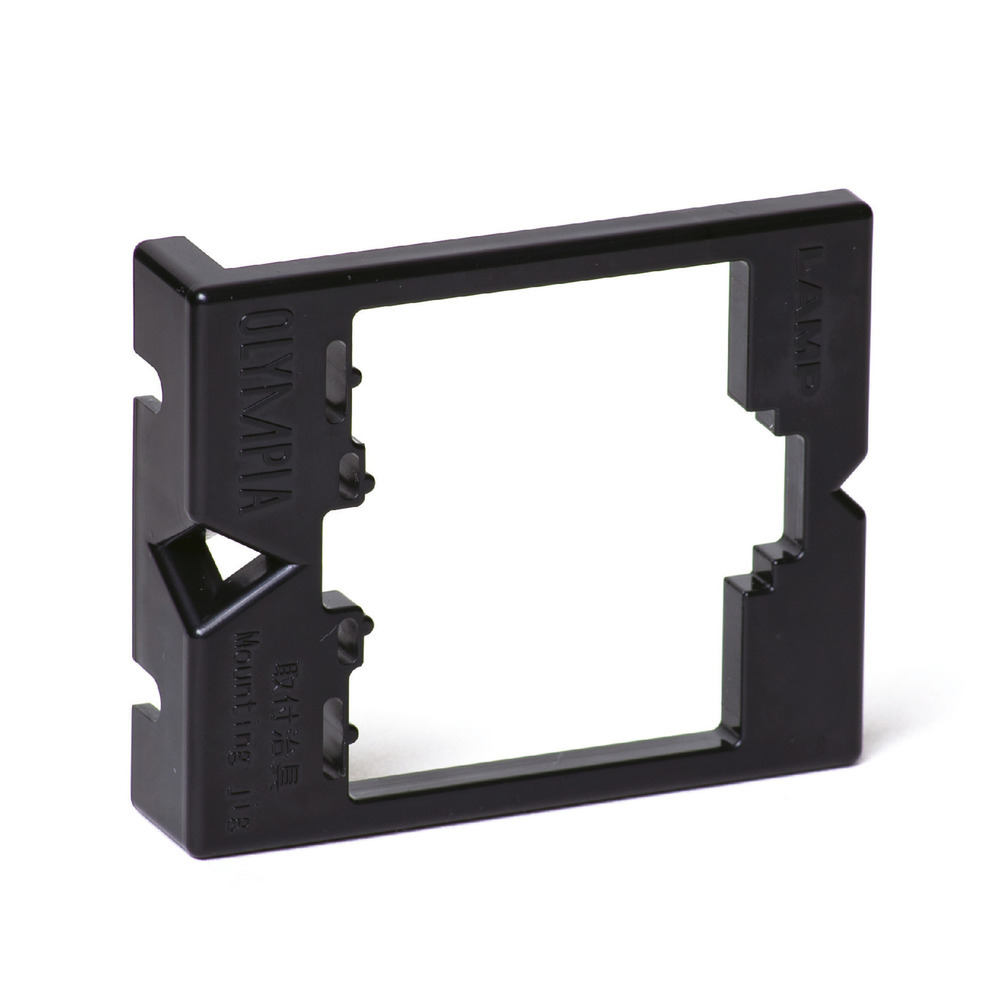
- OLYMPIA Concealed Hinges


OLYMPIA Concealed Hinges


FEATURES


OLYMPIA is the first concealed hinge ever built with Lapcon technology. The innovative rotary damper is not only extremely compact, for sleek overall design, its force can also be adjusted to 5 levels for a perfect match regardless of the door size or weight.


For a piece of furniture to last a lifetime, the hinge must perform flawlessly the whole time. Despite official requirements by JIS (Japanese Standards) asking for only 40,000 cycles, OLYMPIA has cleared 5 times as many (200,000 cycles) to ensure that you will always be able to open and close your doors without worry. (The H360 has passed 100,000 open/close cycles)
[QUICK DEMO] OLYMPIA CONCEALED HINGE Attach/Detach

Depth, vertical, horizontal adjustment screws are all located on top. This was made possible because of our original damper.
[INSTRUCTIONS] OLYMPIA CONCEALED HINGES 3D Adjustment

From the initial design stage to the final inspection of the OLYMPIA hinge, we are proud to stamp it with our LAMP brand, a guarantee of long-term quality.
Product Lineup
Body
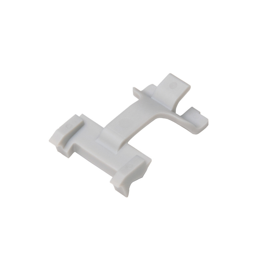
Parts Sold Separately
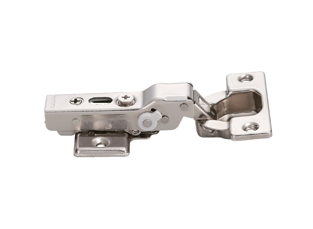
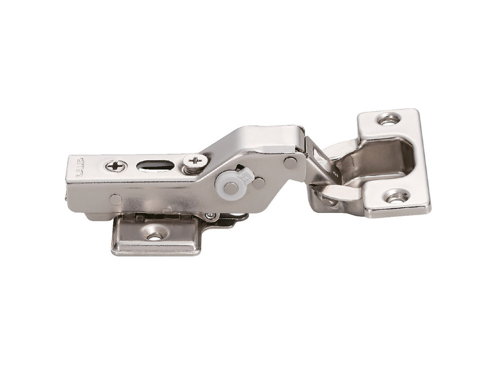
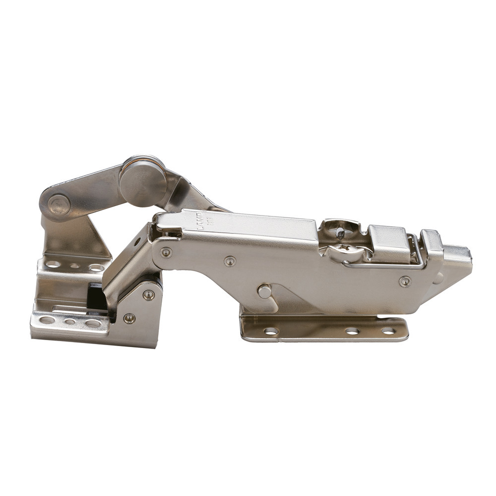
Body: OLYMPIA 360 concealed hinge

Door thickness: wood: 15-20 mm, glass: 4-6 mm / Installation: cup size: Ø35, cup depth: 11 mm
| Opening Angle | Type | Item Code | Item Name | Catch | Damper | Overlay Range | Product Information |
|---|---|---|---|---|---|---|---|
| 105° | 19mm Overlay | 160-026-840 | 360-D26-19T | ○ | 15-19* | CAD/Locus Chart | |
| 160-026-836 | 360-26-19T | ||||||
| 160-026-832 | 360-C26-19T | ○ | |||||
| 160-042-389 | 360-U26-19T (sprung-open) | ||||||
| 14mm Overlay | 160-026-841 | 360-D26-14T | ○ | 10-14* | CAD/Locus Chart | ||
| 160-026-837 | 360-26-14T | ||||||
| 160-026-833 | 360-C26-14T | ○ | |||||
| 160-042-390 | 360-U26-14T (sprung-open) | ||||||
| 9mm Overlay | 160-026-842 | 360-D26-9T | ○ | 5-9* | CAD/Locus Chart | ||
| 160-026-838 | 360-26-9T | ||||||
| 160-026-834 | 360-C26-9T | ○ | |||||
| 160-042-391 | 360-U26-9T (sprung-open) | ○ | |||||
| 93° | Inset | 160-026-843 | 360-D26-0T | ○ | 0 | CAD/Locus Chart | |
| 160-026-839 | 360-26-0T | ||||||
| 160-026-835 | 360-C26-0T | ○ | |||||
| 160-042-392 | 360-U26-0T (sprung-open) | ||||||
| 85° | 19mm Overlay | 160-034-889 | 360-D26-19T85 | ○ | 15-19* | CAD/Locus Chart | |
| 160-034-886 | 360-26-19T85 | ||||||
| 160-034-883 | 360-C26-19T85 | ○ | |||||
| 14mm Overlay | 160-034-890 | 360-D26-14T85 | ○ | 10-14* | CAD/Locus Chart | ||
| 160-034-887 | 360-26-14T85 | ||||||
| 160-034-884 | 360-C26-14T85 | ○ | |||||
| 9mm Overlay | 160-034-891 | 360-D26-9T85 | ○ | 5-9* | CAD/Locus Chart | ||
| 160-034-888 | 360-26-9T85 | ||||||
| 160-034-885 | 360-C26-9T85 | ○ |
* For a bore distance of 5 mm
| Opening Angle | Type | Item Code | Item Name | Catch | Damper | Overlay Range | Product Information |
|---|---|---|---|---|---|---|---|
| 100° | 26mm Overlay | 160-029-084 | H360-D26-26T | ○ | 22-26* | CAD/Locus Chart | |
| 160-029-081 | H360-26-26T | ||||||
| 160-029-078 | H360-C26-26T | ○ | |||||
| 16mm Overlay | 160-029-085 | H360-D26-16T | ○ | 12-16* | CAD/Locus Chart | ||
| 160-029-082 | H360-26-16T | ||||||
| 160-029-079 | H360-C26-16T | ○ | |||||
| 93° | Inset | 160-029-086 | H360-D26-0T | ○ | 0 | CAD/Locus Chart | |
| 160-029-083 | H360-26-0T | ||||||
| 160-029-080 | H360-C26-0T | ○ |
* For a bore distance of 8 mm
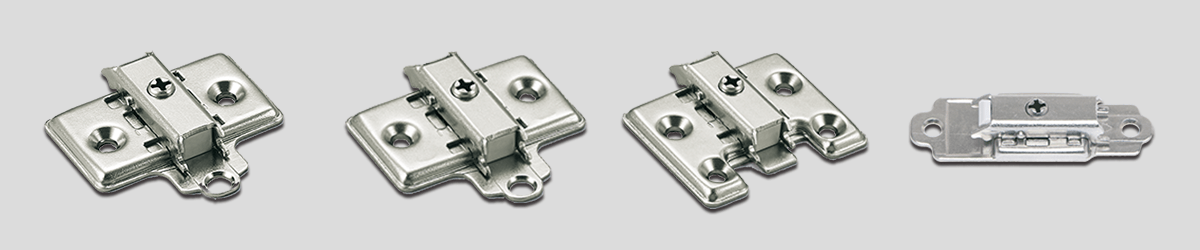
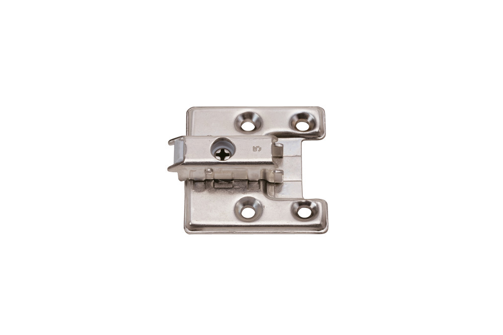
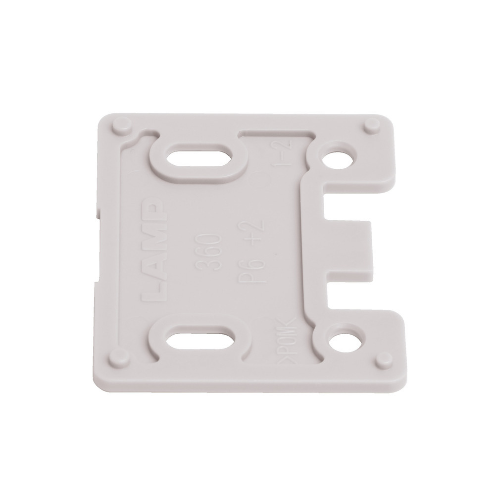
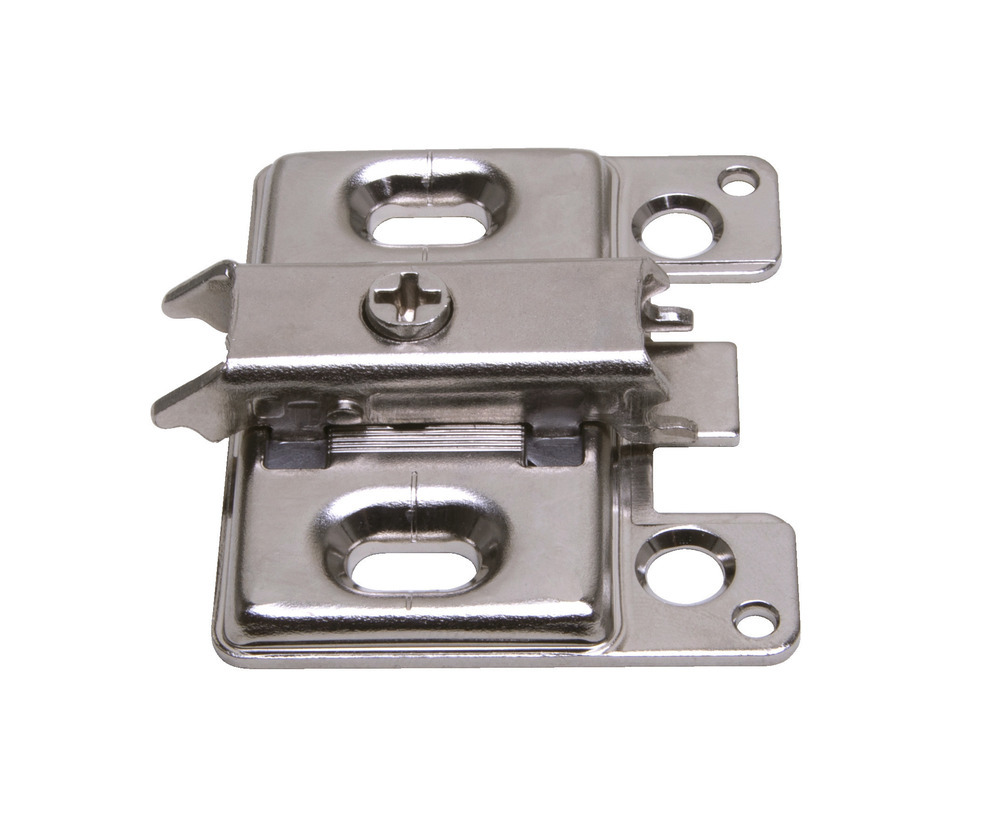
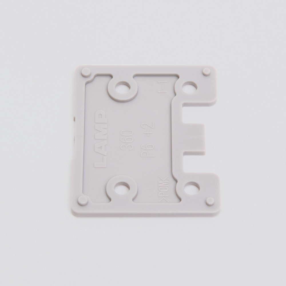
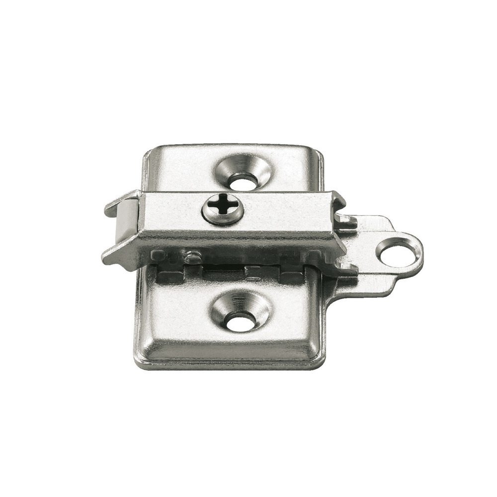
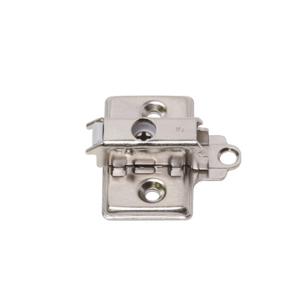
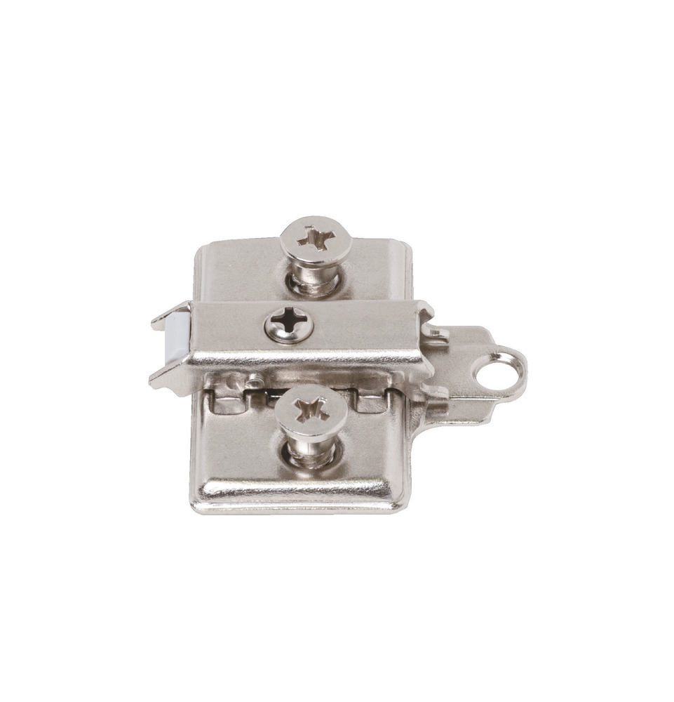
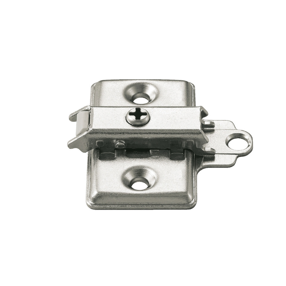
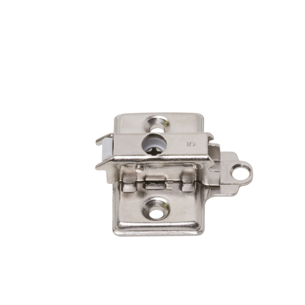
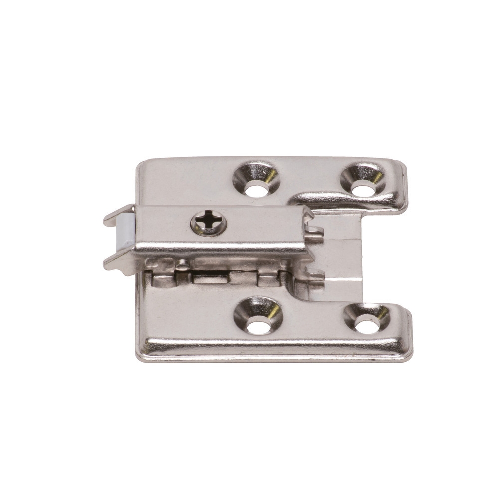
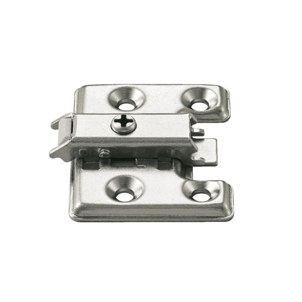
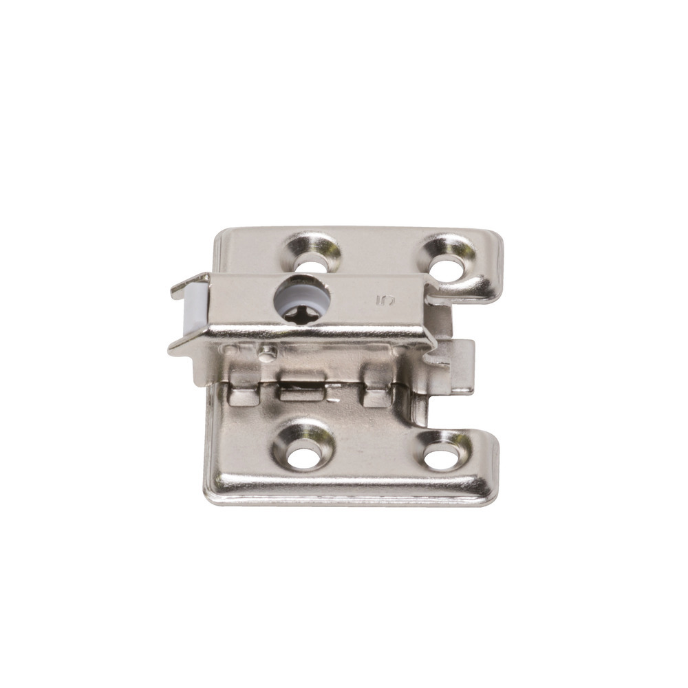
| Pitch | Item Code | Item Name | Type | Product Information |
|---|---|---|---|---|
| System 30 | 160-026-844 | 360-P4W-30T | Standard | CAD |
| 160-035-077 | 360-P4W-30T+5 | Standard+5mm | CAD | |
| 160-042-394 | 360-P4W-30T-DS | Pre-mounted screw | CAD | |
| System 32 | 160-026-845 | 360-P4W-32T | Standard | CAD |
| 160-035-078 | 360-P4W-32T+5 | Standard+5mm | CAD | |
| 160-042-395 | 360-P4W-32T-DS | Pre-mounted screw | CAD | |
| System 32 with 4 holes | 160-026-846 | 360-P6WT | Standard | CAD |
| 160-035-079 | 360-P6WT+5 | Standard+5mm | CAD | |
| 160-042-393 | 360-P6W-30-32T | Standard+7.5* | CAD | |
| 160-050-436 | 360-P6WT-NA | 8mm Depth Adjustment | CAD | |
| Straight | 160-046-697 | 360-P3W-53T | Standard | CAD |
| 160-046-698 | 360-P3W-53T-D10 | With Dowels | CAD |
* Mounting plate positioned 7.5mm closer to the front compared to a standard one.
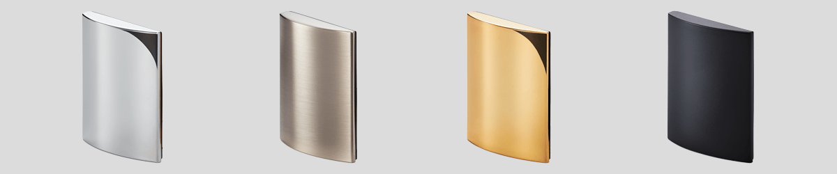
| Item Code | Item Name | Finish / colour | Product Information |
|---|---|---|---|
| 160-043-631 | GH-360FP-CR | Chrome plating | CAD |
| 160-043-632 | GH-360FP-SN | Satin nickel | |
| 160-043-724 | GH-360FP-GP | 24K Gold plating | |
| 160-043-633 | GH-360FP-BL | Black |
| Item Code | Item Name | Product Information |
|---|---|---|
| 160-045-368 | 360-BCS | CAD |
| Item Code | Item Name | Product Information |
|---|---|---|
| 160-042-396 | 360-JIG | CAD |
| Item Code | Item Name | Material | Product Information |
|---|---|---|---|
| 160-070-030 | TAP3515NI | Steel | CAD |
Additional Specifications
Recommended type of damper per installation
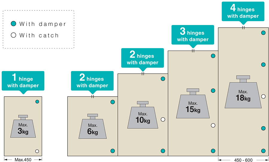
Door size and recommended hinge quantity

- —Please set the door center of gravity as the door center.
- —If you want to increase the door width, please increase the number of hinges accordingly.
- —Attach the upper and lower hinges within 100 mm from the edge of the door.
- —When using three or more, install at regular intervals.
- —Figures shown in the tables above are only indicative.
- —Please always test before finalizing your design.
- —Please contact us for any other configuration.
- —The dimensions of the door and the number of hinges mounted are the results of tests made according to the JIS standard.
- —All screw holes should be used.
Products


Your Recently Viewed Items
You have no recently viewed products.
If you would like to keep track of items viewed, click on the "Keep History" button below.
You have no recently viewed products.
 Loading